The choice of connection method and electronic interface depends on the measurement accuracy required.
3 connection modes can be used for an RTD: 2-wire, 3-wire or 4-wire.
2-Wire measurements
This is the simplest method but results in an error proportional to the length of the cable used for the connection. A standard AWG24 cable (85 Ω/km) introduces an error of the order of 0.42°C per metre of connection for an RTD Pt100 sensor.

The slope and the absolute value are small numbers, especially if we take into account the fact that the measurement wires connected to the sensor can be of several ohms or even tens of ohms. A small wire impedance can contribute to a significant error in our temperature measurement. A wire impedance of 10 ohms results in an error of 10/0.385 or approximately 26°C in this case.

One way of avoiding this problem is to use a measuring device with a bridge. Measurement via a bridge, in this case a Wheatstone bridge, is an indirect indication of the resistance of the RTD. The bridge requires four connection wires, an external source and three resistors which have a temperature coefficient of zero.

3-Wire measurements
The “3-wire” method very often provides a measurement of sufficient quality for the majority of industrial applications. It is based on the hypothesis of equal resistance of the 3 wires. Use of an AWG18 cable (21 Ω/km) introduces an error of less than 0.4°C per 100 m of connection


In order to avoid subjecting the three resistors of the bridge to the same temperature as the RTD, the latter is separated from the bridge by a pair of connecting wires. These wires recreate the problem we saw above: the impedance of the connecting wires affects the temperature reading. This effect can be minimised by using a three-wire bridge configuration. If wires A and B are the same length their impedance effects will cancel each other out because each is in an opposite part of the bridge. The third wire C acts as measuring device in which no current is circulating. The Wheatstone bridge shown in figure 41 creates a non-linear relationship between the change in resistance and the change in the measurement voltage of the bridge. This requires an additional equation to convert the measurement voltage of the bridge into equivalent impedance of the RTD.

4-Wire measurements
This assembly offers the greatest accuracy, as the voltage is measured on the active part of the sensor with a high impedance electronic interface. The resistance of the connection cables no longer affects the measurement error.

The best technique is to use a known source of current and to measure the voltage at the RTD terminals remotely. As no current is circulating in the voltage measurement wires, there is no drop in voltage and therefore no resistance measurement error. The voltage read on the voltmeter is directly proportional to the resistance value of the RTD. The three resistors of the bridge are replaced by a reference resistor enabling the current generated to be accurately established (figure 42). The disadvantage is the need for an additional wire compared with the 3-wire bridge. This is a small price to pay in order to obtain an accurate measurement of the resistance.

Our latest articles

Reading time - 5 min
Upcoming events
Book following dates in your calendar: M+R 2025 – from 03/26/2025 to 03/27/2025 – Antwerp Expo – Stand 3100, Come and visit us! Invitation : https://register.visitcloud.com/survey/22v8m6mjp0fa5?actioncode=NTWO000049WQL&partner-contact=0esxkhcpph1iu…
Why is temperature not a physical quantity like other measurement units?
Temperature is not a quantity in the strict sense of the term as the majority of other measurement units are. A quantity is something which can be increased or decreased, for example length, area, power output, etc. Measuring a quantity…
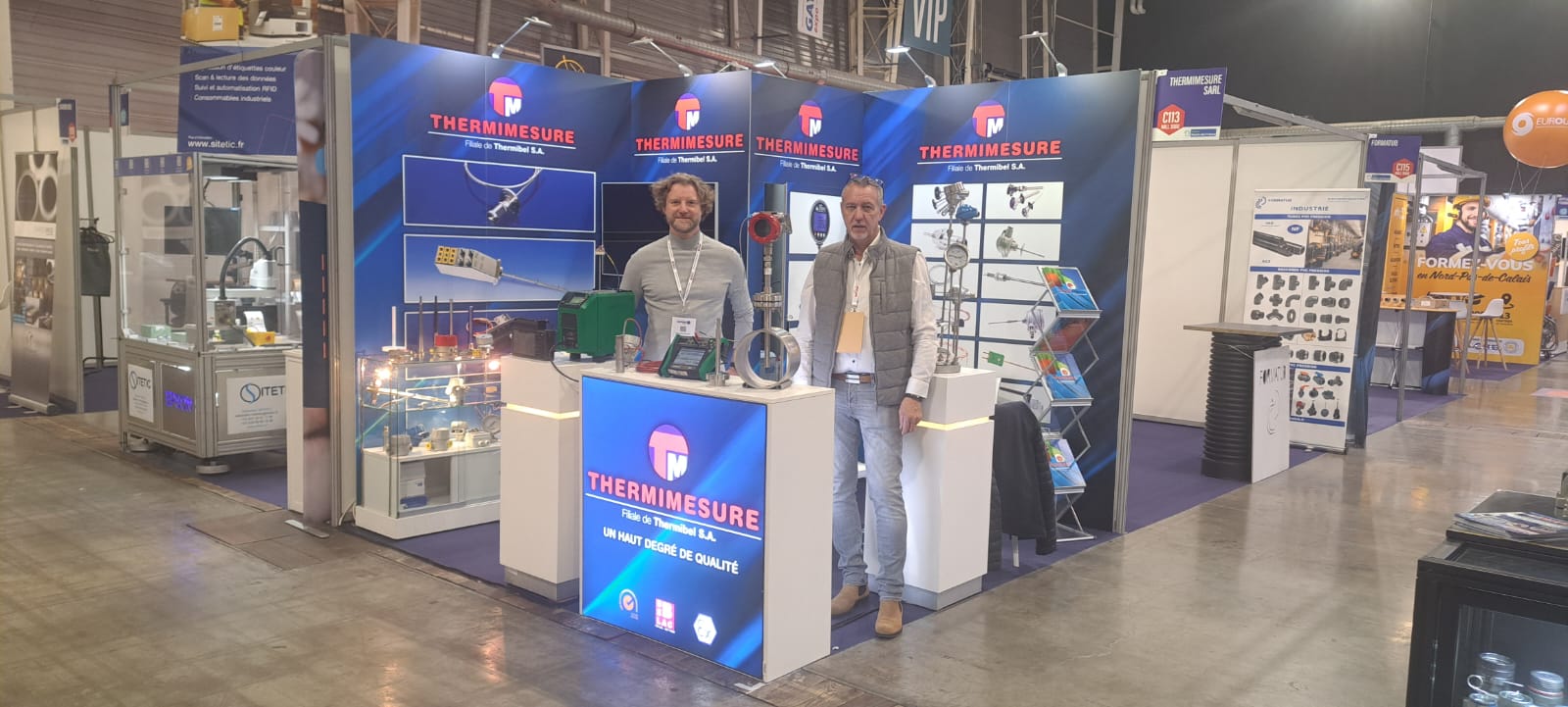
Here we are!
Thermimesure awaits you at SEPEM DOUAI these 27-28 and 29/01/2026 Come one, come all! https://douai.sepem-industries.com/registration/registration…